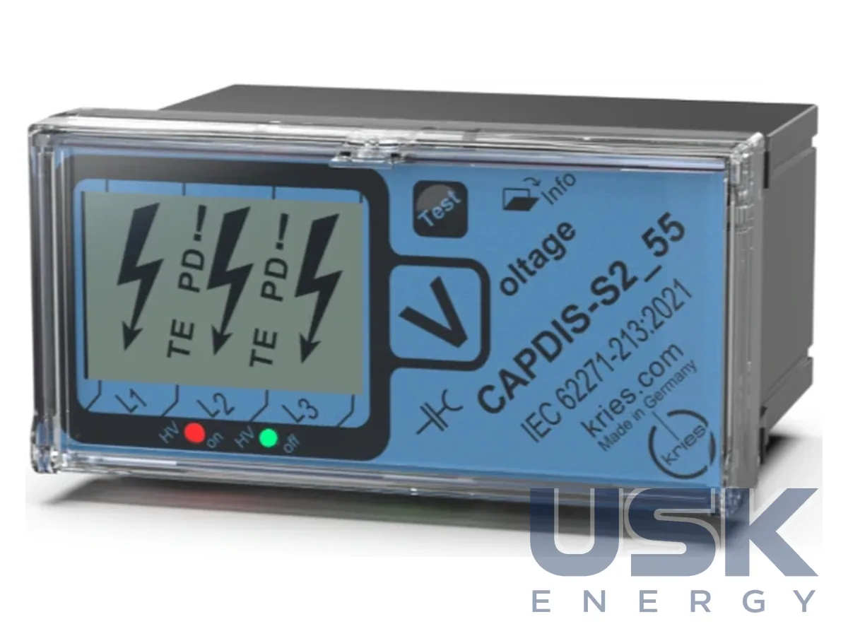
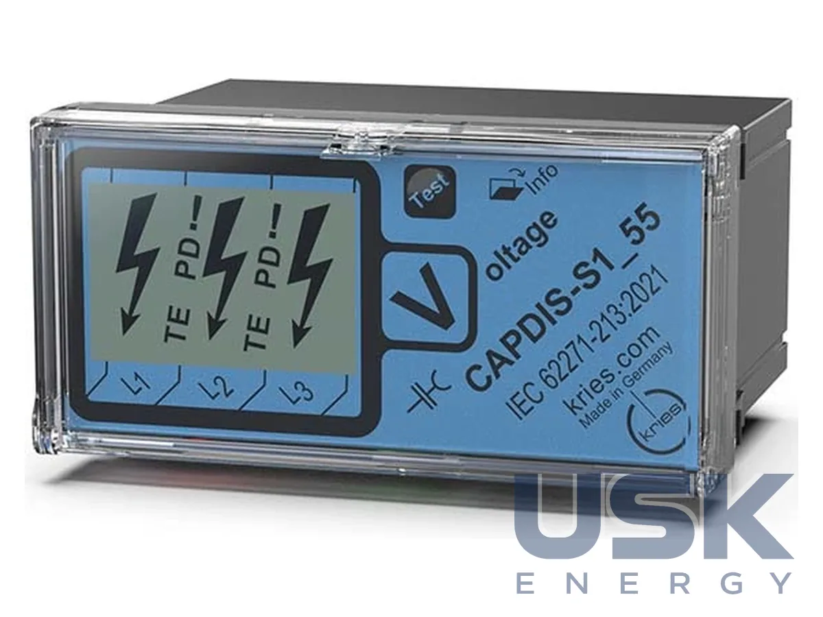
CAPDIS-S1_55 / CAPDIS-S2_55 (R5, R4.5) voltage indicators 1–52 kV for protection circuits and partial discharge detection
Country: Germany · Model: CAPDIS-S1_55 / CAPDIS-S2_55 (R5, R4.5)
A built-in voltage indicator for switchgear (1–52 kV) with continuous three-phase indication. The S2_55 version has two power relays and can work in a protection circuit, and the R5 generation additionally detects partial discharges (PD).
- Voltage class
- 1–52 kV
- Standards
- IEC 61243-5, IEC 62271-213, IEC 60255-1
- PD detection (R5)
- 4 sensitivity levels, switched off with a DIP switch; socket for PD diagnostics
- Relay outputs (S2_55)
- 2 power changeover relays; 250 V AC 5 A / 30 V DC 5 A / 250 V DC 0.3 A
Technical specifications
| Voltage class | 1–52 kV |
|---|---|
| Standards | IEC 61243-5, IEC 62271-213, IEC 60255-1 |
| PD detection (R5) | 4 sensitivity levels, switched off with a DIP switch; socket for PD diagnostics |
| Relay outputs (S2_55) | 2 power changeover relays; 250 V AC 5 A / 30 V DC 5 A / 250 V DC 0.3 A |
| Auxiliary supply (S2_55) | 24–230 V AC/DC ± 10 %, < 1 W |
| Protection functions | reverse voltage monitoring, earthing switch interlock, warning about island mode |
| Enclosure | 48 × 96 × 37 mm, IP54 |
| Operating temperature | −25 … +55 °C |
| Self-test | battery-free (patent DE 103 04 396) |
Specifications are taken from the manufacturer’s technical documentation. Updated .
Description
The device complies with IEC 62271-213:2021 and IEC 61243-5, and S2_55 also with IEC 60255, so it is introduced into the protection circuit and into safety-related functions. The three-step level indication does not require repeated tests per IEC 62271-213 and BGV A3, and the self-test works without a battery. On all inputs and outputs, S2_55 suppresses high-frequency interference from atmospheric overvoltages, restrikes and resonant oscillations, so it does not get into the rest of the secondary equipment. For networks with distributed generation, reverse voltage monitoring is provided, at which the earthing switch is blocked. When the circuit breaker is open, the device sends a signal about island mode to the bay control unit and excludes automatic reclosing onto voltage. Two relays with changeover contacts of 250 V AC, 5 A are powered from 24–230 V, and the state is shown by LEDs. In the R5 version, the critical PD level is output to the display and to the general fault relay, the sensitivity has 4 levels and is switched off with a DIP switch at the rear. Behind the front cover there is a PD diagnostics socket, and the PD-Trend-Check accessory changes the threshold from the front. Together with IKI-23, IKI-50 and IKI-55, the device builds a PD trend (integration 24 h, trend 72 h). The panel-mount enclosure is 48 × 96 × 37 mm, IP54, operating temperature −25…+55 °C, and there are interfaces to CAPDIS-M and LRM.
How to choose
First determine whether relays are needed. S1_55 has no relay and no auxiliary power, it is just an indicator. Take S2_55 if you need to block the earthing switch, exclude automatic reclosing or send a signal to relay protection. The R5 generation adds PD detection, and R4.5 only shows voltage. For switchgear of 53–480 kV there are CAPDIS-S1_HV / S2_HV, for 1–52 kV with an LRM interface CAPDIS-S1+ / S2+ is suitable, and for replacing old indicators with an HR interface there is CAPDIS-PI.
Request a price and lead time
CAPDIS-S1_55 / CAPDIS-S2_55 (R5, R4.5) voltage indicators 1–52 kV for protection circuits and partial discharge detection. We reply within one business day.
Or email office@usk.ua or call +38 (044) 339-50-20.
FAQ
What is the difference between CAPDIS-S1_55 and CAPDIS-S2_55?
S1_55 works without a relay and auxiliary power and only indicates voltage. S2_55 has 2 changeover relays, is powered from 24–230 V AC/DC and complies with IEC 60255 for protection circuits.
For which switchgear voltage is this indicator suitable?
For switchgear of class 1–52 kV per IEC 62271-213 and IEC 61243-5. For 53–480 kV, CAPDIS-S1_HV or S2_HV is needed.
Is a battery needed for the self-test?
No, the self-test is performed without a battery. The three-step indication does not require repeated tests per IEC 62271-213 and BGV A3.
How is the sensitivity to partial discharges set in the R5 version?
The sensitivity has 4 levels, which are selected or switched off with a DIP switch on the rear wall. The threshold can be adjusted from the front with the PD-Trend-Check accessory.
Similar products
REQUEST
Need a price, lead time or replacement?
Send us a request and we will confirm the configuration, lead time and delivery terms. We reply by email.